This tutorial shows how to connect the NEO-6M GPS module with the ESP32 development board, get the GPS data and publish latitude and longitude positions to the AskSensors IoT cloud in real time over MQTT protocol.
Note: For the purpose of test, we used a mobile WiFi Hotspot, However, if you intend to implement such kind of GPS tracker in final products, you may need to integrate a GSM LTE/4G module onboard.
1) Prerequisites :
Followings are the prerequisites and backgrounds concepts you need to completely understand this tutorial and build connected GPS tracking and navigation systems with ESP32 and AskSensors.
- AskSensors account subscription (The map chart used in this tutorial is only available for paid or 15 days free trial accounts).
- Create a new sensor device with at least one module to show your GPS position.
- Now after this click on ‘Add graph’ and select a Map graph type.
- Copy down your Sensor device API KEY IN, we will use it later.
- Get familiar with the AskSensors MQTT API.
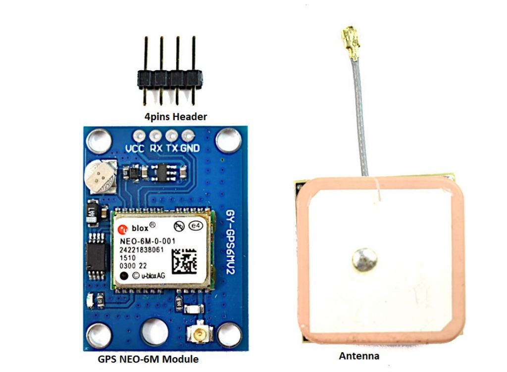
2) GPS receiver specifications
Basically, GPS (Global Positioning System) receivers work by figuring out how far they are from a number of satellites. They are pre-programmed to know where the GPS satellites are at any given time and then calculate the location on Earth using the well known Trilateration process. The more satellites there are above the horizon the more accurately your GPS unit can determine where you are.
This project uses the low power NEO-6M GPS module from u-blox, suitable for battery powered, inexpensive, easy to interface with microcontrollers and insanely popular among hobbyists.
Characteristics:
- Power supply: 2.7V to 3.6V
- Default baud rate: 9600 bps
- Current consumption: 45mA.
- Up to 22 satellites on 50 channels tracking
- Up to 5 location updates a second with 2.5m Horizontal position accuracy.
- Navigation Sensitivity: Up to -161 dBm
- Navigation Update Rate: 1Hz
- Comes with an external antenna and built-in EEPROM.
- Interface: RS232 TTL with Serial Baud Rate 4800-230400 (default 9600)
- Operating Temperature: -40°C ~ 85°C
- Communication Protocol: UBX Binary, RTCM and Standard NMEA output: To know what each data field means in each of these sentences, you can consult NMEA data here.
In this tutorial, we are going to use the TinyGPS++ library to convert those NMEA messages into a readable and convenient format.
3) Hardware Used
- NEO-6M GPS module
- ESP32 development board.
- Breadboard
- Jumper wires
- Computer running Arduino IDE software.
- USB micro cable to connect ESP32 development board to the computer.
- A WiFi Hotspot
4) Hardware Set up
The GPS module will be powered with 3.3V power supply. It communicates with the ESP32 via serial communication using the TX and RX pins available on the 4pins header. The following image shows the schematic diagram of the circuit used in this tutorial.

- Connect the VCC pin of the GPS module to the ESP32 3.3V pin.
- Connect the GPS ground pin to the ESP32 ground pin.
- Now, connect the RX pin of the GPS module to the TX pin of the ESP32. Similarly, connect the TX pin of the GPS module to the RX pin of the ESP32 (RX and TX pins of the ESP32 are defined in the software).
- Last, connect your ESP32 to the computer through a USB cable. The ESP32 will be powered from the USB 5V.
4) Install the ESP32 in Arduino IDE
The ESP32 will be programmed using Arduino IDE. There’s an add-on for the Arduino IDE (1.8.7 or higher) that allows you to program the ESP32 using the Arduino IDE and its programming language. Follow the instructions below:
- Open the preferences window from the Arduino IDE : File> Preferences.
- Go to the “Additional Board Manager URLs” field, Enter the following URL:
https://dl.espressif.com/dl/package_esp32_index.json
- If you already have the ESP8266 boards URL, separate the URLs with a comma as shown below:
https://dl.espressif.com/dl/package_esp32_index.json, http://arduino.esp8266.com/stable/package_esp8266com_index.jso
- Open boards manager (Tools > Board > Boards Manager), search for ESP32 and click the install button for the “ESP32 by Espressif Systems”.
5) Libraries Used
- TinyGPS++ Library:
This library makes it simple to get the latitude and longitude in a format that is useful and easy to publish to the AskSensors cloud.
- Download the TinyGPSPlus library. You should have a .zip folder in your Downloads folder
- Unzip the .zip folder and you should get TinyGPSPlus-master folder
- Rename your folder from TinyGPSPlus-master to TinyGPSPlus
- Move the TinyGPSPlus folder to your Arduino IDE installation libraries folder
- Finally, re-open your Arduino IDE
Note: The NEO-6M GPS module works with 9600 baud rate. The examples provided in the TinyGPS++ library (File > Examples > TinyGPS++) uses a baud rate of 4800 for the GPS module and need to be changed to 9600.
- EspSoftwareSerial Library:
- Download the espsoftwareserial library from github.
- Unzip the .zip folder and you should get espsoftwareserial-master folder
- Rename your folder from espsoftwareserial-master to espsoftwareserial
- Move the espsoftwareserial folder to your Arduino IDE installation libraries folder
- Finally, re-open your Arduino IDE
- PubSubClient library:
This library provides a client for doing simple publish/subscribe messaging with a server that supports MQTT.
- Download the PubSubClient library from github.
- Unzip the .zip folder and you should get pubsubclient-master folder
- Rename your folder from pubsubclient-master to pubsubclient
- Move the pubsubclient folder to your Arduino IDE installation libraries folder
- Then, re-open your Arduino IDE
Note: The library comes with a number of example sketches that are not fully compatible with the ESP32. However, the example provided in this tutorial is working very reliably in the Arduino IDE software.
6) Software Setup
Download this complete demo from the AskSensors github page. You need to edit the following parameters:
<span style="color: #993300;">const char* ssid = ".................."; // Wifi SSID</span>
<span style="color: #993300;">const char* password = ".................."; // Wifi Password</span>
<span style="color: #993300;">const char* username = "................."; // my AskSensors username</span>
<span style="color: #993300;">const char* pubTopic = "publish/..../....."; // publish/username/apiKeyIn</span>
<span style="color: #993300;">const unsigned int writeInterval = 25000; // write interval (in ms)</span>
<span style="color: #993300;">static const int RXPin = 16, TXPin = 17; // UART pinout</span>
The Serial Monitor is left on the code for debugging purposes. They can be removed in the final output to save memory.
7) Running the code
- First, Make sure that your WiFi Hotspot is powered on.
- Connect your ESP32 board to your computer through the micro-USB cable. Make sure the power LED goes high on the module to ensure power supply.
- Open your Arduino IDE and select Tools options for your ESP32 board type and serial port where it’s connected then click upload. The code will be running automatically after Reset.
- Open the serial terminal to supervise the ESP32 software sequence step by step.
- Now, we will return back to the AskSensors web application to monitor the GPS Tracker map updated by the ESP32 development board based on data parsed from GPS NEO-M6 Module. You should get a map graph showing your latest GPS position as shown below.

- In addition, you can show your trajectory in the map by enabling the “Show line” and “Show location history”. You can also customize the colors as you want.

- The map below presents an example of locations data logged during a little walk in the street.

8) Source code
A basic source code is shown below. Please refer to the AskSensors Github page to get the latest version and updates.
<span style="color: #993300;">/*</span>
<span style="color: #993300;">* MQTT and AskSensors IoT Platform</span>
<span style="color: #993300;">* Description: ESP32 publishes NEO-6M GPS position to AskSensors using MQTT</span>
<span style="color: #993300;">* Author: https://asksensors.com, 2020</span>
<span style="color: #993300;">* github: https://github.com/asksensors</span>
<span style="color: #993300;">*/</span>

<span style="color: #993300;">#include <WiFi.h></span>
<span style="color: #993300;">#include <PubSubClient.h></span>
<span style="color: #993300;">#include <SoftwareSerial.h></span>
<span style="color: #993300;">#include <TinyGPS++.h></span>

<span style="color: #993300;">//TODO: ESP32 MQTT user config</span>
<span style="color: #993300;">const char* ssid = ".................."; // Wifi SSID</span>
<span style="color: #993300;">const char* password = ".................."; // Wifi Password</span>
<span style="color: #993300;">const char* username = "................."; // my AskSensors username</span>
<span style="color: #993300;">const char* pubTopic = "publish/..../....."; // publish/username/apiKeyIn</span>
<span style="color: #993300;">const unsigned int writeInterval = 25000; // write interval (in ms)</span>

<span style="color: #993300;">static const int RXPin = 16, TXPin = 17;</span>
<span style="color: #993300;">static const uint32_t GPSBaud = 9600;</span>
<span style="color: #993300;">//AskSensors MQTT config</span>
<span style="color: #993300;">const char* mqtt_server = "mqtt.asksensors.com";</span>
<span style="color: #993300;">unsigned int mqtt_port = 1883;</span>

<span style="color: #993300;">// objects</span>
<span style="color: #993300;">WiFiClient askClient;</span>
<span style="color: #993300;">PubSubClient client(askClient);</span>
<span style="color: #993300;">TinyGPSPlus gps; // The TinyGPS++ object</span>
<span style="color: #993300;">SoftwareSerial ss(RXPin, TXPin); // The serial connection to the GPS device</span>

<span style="color: #993300;">// setup</span>
<span style="color: #993300;">void setup() {</span>
<span style="color: #993300;">Serial.begin(115200);</span>
<span style="color: #993300;">Serial.println("*****************************************************");</span>
<span style="color: #993300;">Serial.println("********** Program Start : ESP32 publishes NEO-6M GPS position to AskSensors over MQTT");</span>
<span style="color: #993300;">Serial.print("********** connecting to WIFI : ");</span>
<span style="color: #993300;">Serial.println(ssid);</span>

<span style="color: #993300;">WiFi.begin(ssid, password);</span>

<span style="color: #993300;">while (WiFi.status() != WL_CONNECTED) {</span>
<span style="color: #993300;">delay(500);</span>
<span style="color: #993300;">Serial.print(".");</span>
<span style="color: #993300;">}</span>
<span style="color: #993300;">Serial.println("");</span>
<span style="color: #993300;">Serial.println("->WiFi connected");</span>
<span style="color: #993300;">Serial.println("->IP address: ");</span>
<span style="color: #993300;">Serial.println(WiFi.localIP());</span>

<span style="color: #993300;">client.setServer(mqtt_server, mqtt_port);</span>
<span style="color: #993300;">client.setCallback(callback);</span>
<span style="color: #993300;">// GPS baud rate</span>
<span style="color: #993300;">ss.begin(GPSBaud);</span>

<span style="color: #993300;">}</span>
<span style="color: #993300;">// loop</span>
<span style="color: #993300;">void loop() {</span>

<span style="color: #993300;">if (!client.connected()) </span>
<span style="color: #993300;">reconnect();</span>
<span style="color: #993300;">client.loop();</span>
<span style="color: #993300;">// This sketch displays information every time a new sentence is correctly encoded.</span>
<span style="color: #993300;">while (ss.available() > 0)</span>
<span style="color: #993300;">if (gps.encode(ss.read()))</span>
<span style="color: #993300;">displayInfo();</span>

<span style="color: #993300;">if (millis() > 5000 && gps.charsProcessed() < 10)</span>
<span style="color: #993300;">{</span>
<span style="color: #993300;">Serial.println(F("No GPS detected: check wiring."));</span>
<span style="color: #993300;">while(true);</span>
<span style="color: #993300;">}</span>
<span style="color: #993300;">}</span>

<span style="color: #993300;">// GPS displayInfo</span>
<span style="color: #993300;">void displayInfo() {</span>

<span style="color: #993300;">if (gps.location.isValid()) {</span>
<span style="color: #993300;">double latitude = (gps.location.lat());</span>
<span style="color: #993300;">double longitude = (gps.location.lng());</span>

<span style="color: #993300;">Serial.println("********** Publish MQTT data to ASKSENSORS");</span>
<span style="color: #993300;">char mqtt_payload[50] = "";</span>
<span style="color: #993300;">snprintf (mqtt_payload, 50, "m1=%lf;%lf", latitude, longitude);</span>
<span style="color: #993300;">Serial.print("Publish message: ");</span>
<span style="color: #993300;">Serial.println(mqtt_payload);</span>
<span style="color: #993300;">client.publish(pubTopic, mqtt_payload);</span>
<span style="color: #993300;">Serial.println("> MQTT data published");</span>
<span style="color: #993300;">Serial.println("********** End ");</span>
<span style="color: #993300;">Serial.println("*****************************************************");</span>

<span style="color: #993300;">delay(writeInterval);// delay </span>
<span style="color: #993300;">} else {</span>
<span style="color: #993300;">Serial.println(F("INVALID"));</span>
<span style="color: #993300;">}</span>

<span style="color: #993300;">}</span>

<span style="color: #993300;">//MQTT callback</span>
<span style="color: #993300;">void callback(char* topic, byte* payload, unsigned int length) {</span>
<span style="color: #993300;">Serial.print("Message arrived [");</span>
<span style="color: #993300;">Serial.print(topic);</span>
<span style="color: #993300;">Serial.print("] ");</span>
<span style="color: #993300;">for (int i = 0; i < length; i++) {</span>
<span style="color: #993300;">Serial.print((char)payload[i]);</span>
<span style="color: #993300;">}</span>
<span style="color: #993300;">Serial.println();</span>
<span style="color: #993300;">}</span>
<span style="color: #993300;">//MQTT reconnect</span>
<span style="color: #993300;">void reconnect() {</span>
<span style="color: #993300;">// Loop until we're reconnected</span>
<span style="color: #993300;">while (!client.connected()) {</span>
<span style="color: #993300;">Serial.print("********** Attempting MQTT connection...");</span>
<span style="color: #993300;">// Attempt to connect</span>
<span style="color: #993300;">if (client.connect("ESP32Client", username, "")) { </span>
<span style="color: #993300;">Serial.println("-> MQTT client connected");</span>
<span style="color: #993300;">} else {</span>
<span style="color: #993300;">Serial.print("failed, rc=");</span>
<span style="color: #993300;">Serial.print(client.state());</span>
<span style="color: #993300;">Serial.println("-> try again in 5 seconds");</span>
<span style="color: #993300;">// Wait 5 seconds before retrying</span>
<span style="color: #993300;">delay(5000);</span>
<span style="color: #993300;">}</span>
<span style="color: #993300;">}</span>
<span style="color: #993300;">}</span>
9) Conclusion
The GPS alone is a formidable device. When connected to the cloud, it can be used for smart Navigation and Tracking applications. This tutorial described how to connect the GPS NEO-6M module with the ESP32 to the AskSensors cloud. It can serve as a good launch pad for anyone looking to get into the world of IoT cloud based GPS tracking systems.
Please feel free to comment.


